Introduction
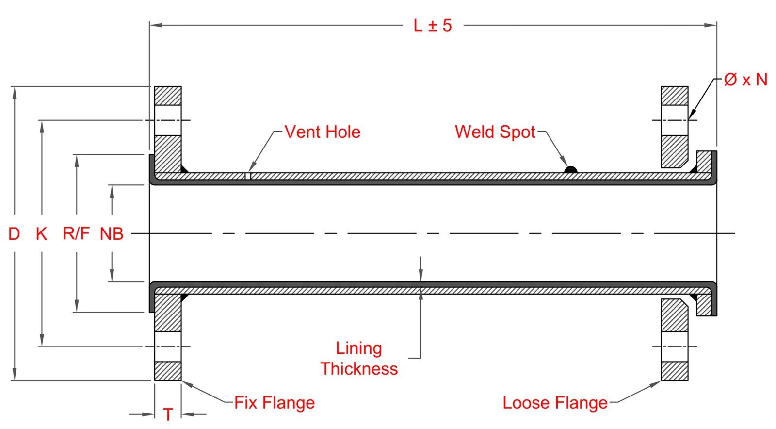
Our PFA lined cross is available in sizes ranging from 25 mm to 300 mm in diameter, with lining thickness varying from 3 mm to 8 mm depending on the size. It is constructed with a durable outer body of carbon steel or stainless steel for mechanical strength, while the inner surface is lined with high-performance fluoropolymers such as PTFE, PFA, or FEP, ensuring excellent chemical resistance and an inert flow path. Our PFA lined cross fittings are suitable for full vacuum applications, ensuring reliable performance under negative pressure conditions.